
Home | Observatory | Eos Driver Maxim/DL | Weather | Releated Links | Contact Us
Construction of Bear Creek Observatory
Stage 1 � Research
After hauling around the new 12� LX-200GPS to several star parties, and 10 days of dark sky observing in northern Idaho in the back yard of my good friend Ed, I realized it was not a scope that invited hit-and-run astronomy. It needed a more permanent home. Besides the considerable weight, the setup cost made a night�s worth of astronomy more work than it was worth for the most part; especially when astrophotography was involved. I first settled on our upstairs roof-top porch. It was very solid, close to the bedroom computer and provided a safe and stable location to setup the scope. I rigged a silver cover out of Mylar emergency camping blankets. The scope could sit outside day and night and remain parked between sessions. I could operate the scope remotely from my downstairs office while I remained warm and dry. This was nearly ideal; quick setup, easy access and a reasonable sky view. The downsides were that I needed to move most of the electronics, cables and optics inside after each session and cover the scope. There was also light pollution from the house and we had to avoid heavy steps to avoid vibrating the scope. I also started noticing some rust on some Allen bolts, and the declination clutch was getting sticky. While the dew heaters kept the corrector plate and Telrad dry the rest of the scope was saturated nightly. I also liked to setup a series of automated shots, but this would mandate staying up till the end or waking up to put everything away and cover the scope. After seeing Ajai Sehgal�s ProDome 10 I really saw the advantage of automating the telescopes environment as well as the scope and camera. He did not even need to be in the same state (or country!). My first thought was to make a sliding roof for the porch area. While this was attractive at first, I realized that I was in for a permit. I also realized that a permanent pier was nearly impossible. I also studied the year round effects of view occlusion to my imaging possibilities and did not like how much was obstructed by the roofline, chimney and trees. The final straw came when my wife told me she would not give up the porch access to a dome or sliding roof.
From there I decided to look into the various commercial domes on the market. The one I liked the most was the Technical Innovations Pro-Dome , but it was probably a $10k+ project and had some fatal flaws. It was tight for visual observing, and could not be opened during the rain. This meant that all rigging must be done in the dry. Good luck in Seattle! Working on hardware during the rainy season was a must. I looked into other options. Several ranged into the $50k range and up for metal domes with full automation. I was not interested in spending that sort of money. I like working with my hands and I have had a long love of both carpentry and microcontroller electronics. I stated toying with the idea of building my own observatory. I looked around on the internet and saw a number of people who had build observatories of all kinds. Two that caught my eye as being reasonably cost effective and functional were Joe's foam geodesic dome, and Michael Cook�s wood dome. Michael built his dome 20 years ago but kept photos and documented his work very well. I had conceived of my own plywood rib dome design and when I saw his plans I was shocked at how similar they were. He had worked out some details I have not thought of yet, so it seemed like good place to start. The alternative was the foam and fiberglass Geodesic dome, but I helped my cousin build a surfboard when I was a kid, and I itched for a week from the fiberglass. This loathing of fiberglass work has kept me from building a kit plane so far. That and the cutting and assembling of several hundred foam boards seemed like allot of work.
I started by printing out and examining Michael Cook�s plans . I liked the level of detail he provided, but as I spend more time I realized that he evidently had more time than money. His design called for spending more that 300 man hours cutting out 2 foot long plywood arks and then gluing them together to form the dome rings and ribs before even beginning to assemble the dome. While this might have been efficient use plywood, it was significant time investment and I am sure that the short sections compromised the structural integrity of the end components. He built an observatory for mostly manned visual observing. I wanted a fully robotic remote observatory, with the option of having a local image processing and computer workstation. I also did not want the tight quarters, and wanted to be able to separate computer light contamination from the scope.
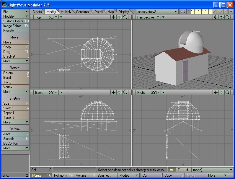
Staring from Michael�s plans I began drawing up my own designs in Lightwave 3D. Lightwave is primarily a 3d animation package, but it has an efficient model editor that can do accurate dimensional measurement and design. I also soon realized that I could use the 3d models to simulate the observatory state for remote monitoring and control after the dome was built.
At fist I added a squared off section to one side of the base cylinder to accommodate more floor space. I then realized that the base should be higher. Then I needed a roof for the square floor space. I modeled the structure and rendered a view of it. I decided it was time to decide where this should go. We have a 4 acre lot, with clear southern view and trees on the North side of the property. The south horse pasture was the best location from the sky-view standpoint. I decided to composite a rendering of the observatory onto a digital picture of the pasture and barn. I was trying to decide where it should go and I repeatedly had to work around the existing woodshed that was in the pasture. My wife was looking over my shoulder and said �Why don�t you just put the dome on the woodshed�. I thought for a few seconds and then I ran out to the pasture to inspect the existing structure. It was an 8� x 16� building with a 4x6 frame structure. It had sheeting and siding to match the house and barn on 2 sides. It was on a concrete slab foundation and it was seriously overbuilt. As I started comparing, I realized that this was the perfect base building for the dome. All I needed was to mate the dome support cylinder to the 4x6 roof support framing, cut a hole thru the existing roof, pour a concrete pier, enclose the final two walls and add a door. Bingo, I have the observatory! This soon became the plan of action.
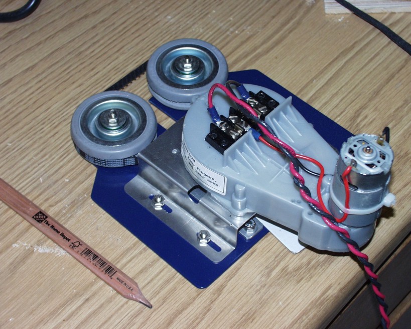
For the automation I decide that I wanted to build the microcontroller hardware and write the software, but the motors, gearing and cable rigging would have to be commercial quality or I would not get reliable operation. I sourced the driver motors for the dome and shutter, along with some cable rigging from Technical Innovations, makers of the HomeDome and ProDome. They wanted $800 for two driver motors, a complete shutter rigging system and power supply. They wanted an additional $1400 for the computer control system and another $650 for weather interlock. I decided I would build my own computer control and use a Radio Shack $400 wireless weather station instead of buying from them.
I took my plans to once carpenter and a contractor. I did not like either the prices or the timeframe, so I figured that I would have to do the work myself if I wanted to get it done. I made a comprehensive takeoff of my plans and priced the materials at Home Depot. Combined with the $800 for the motors, I figured the materials totaled about $2000, with maybe another $500 to drywall and frame the woodshed.
Stage 2: Construction:
My first free Saturday (9/28/02) came and I realized I would have to make room for the project. I spend 10 hours that day rearranging my garage and workshop area and then bought the first round of tools and materials.
I chose paint grade 3/4� plywood that sold for $35 a sheet. I needed almost 10 sheets. The substantial scrap might come in handy for some other project, but my ring and rib design would take one tenth the time that Michael Cook�s system would have been. At my hourly rate I figure that buys a lot of plywood and I still come out on top. I purchased most of the tools and enough fasters to get started with.
The day was shot on cleanup so I unloaded the material into my nice, clean, organized garage and called it a day.
The next Saturday I started by creating a jig out of 1x2 lumber to create the template for cutting. I drilled a hole for a standard pencil on one end, and drilled a number of index holes ad various radiuses foe each of the inner and outer radiuses that each arch would need to be cut. I also created a jig to locate the center point off the center of the 4x8 sheets I was using. Once you marked the 4� center of the sheet, you could get one Half circle arc, and at least four � circle arcs out of each 4x8 sheet.
I traced the inner and outer lines of each rib, then drew connected then at the ends with a line drawn perpendicular to the tangent line 45 degrees apart. I will attach a drawing of the template and the jig to make it.
The cutting of the ribs was done with a Bosch jigsaw . I used the �0� setting with a medium fine cutting blade to get a descent cut without making a mess of the plywood. After finishing the fist set of arcs and fitting them together I realized that the quality of my curves would not hack it. I kept moving anyway.
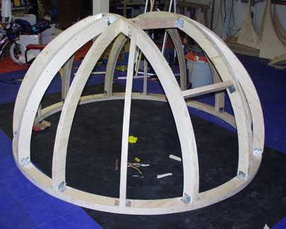
I glued the parts together then fastened them together with 1 � #6 fine drywall screws. After finishing two layers the ring seemed strong, but had some flex and could easily be shaken and stated oscillating. With the third layer it became absolutely solid and rigid. There was no noticeable deformation or oscillation under any load. Now altogether I found that on average it was round, but each board waved in and out randomly from the next.
The cure to the waves was the purchase of a handheld belt sander. With 50 and 80 grit paper I was able to sand out all the waved and make what was a nearly perfect base ring that looked like if have been professionally laminated as one piece. You could not tell it had been 3 layers of �. The sander made my hacked cutting job completely irrelevant.
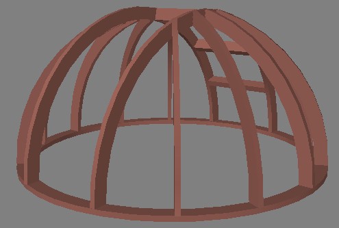
After the base ring, there were a ton of ribs to do. Progress picked up as I grew more comfortable. I finally measured and marked the two main hoops and attached them with steel L braces and some bendable angle braces. The structure was incredibly solid. I tried using it as parallel bars and they held my weight with no deflection at all. I think my dome was going to be overkill.
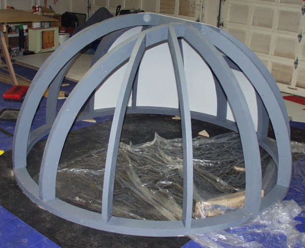
Tuesday night I stayed up late and primed the dome structure. It looked great painted. Wednesday my good friend Reese and I took vacation days and proceeded to skin the dome. I was undecided at what material I wanted to use. Michael Cook used masonite in his design. Other domes I have seen used thin plywood, others chicken wire and mortar, others used fiberglass. I had sourced some 8x4 sheet plastic that seemed flexible enough to fit the curves, rigid enough for strength and waterproof. It has texture that will not require painting, but would accept it. We tried to sample fit one set. While trying the masonite, Reese forced it around a tight curve and it broke. I decided that we would have to go with the plastic, even though it was 5 times the price, I figured it would last much longer.
It stated slowly, but after we got a couple of the ribs spanned it was apparent that it would look really good. We are going to cover that nail holes with calking and pine trim, primed and painted white. By the time we bought all the material at Home Depot half the day was gone. We managed to tear the second gore we attempted while trying to pull a nail up by the plastic board. When it tore, I realized it was a composite material with the dreaded fiberglass. Aghhh! We finished 1/3 of the dome. I will probably try some myself in the evenings this week, but for now I am itching like crazy on my arms from cutting the material. The fiberglass gets in you and makes you itch for days. Next time long sleaves.
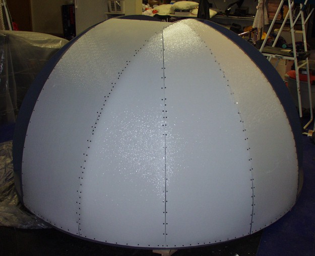
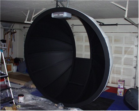
The Dome Gets Skinned:
Well I finally got the dome skinned completely. This has been the messiest part of the project. The plastic is hard to work with and the fiberglass dust is a pain. It is also the least exact science since we are doing the impossible of wrapping a flat plane around a m compound curvature in both x & y. This is the same sort of problem as mapping a star chart of the full sky onto a flat monitor. I was able to prime and paint the interior of the dome and it looks great. The flat black makes it pitch dark inside the dome. It took a good deal of work to get a photo that showed any soft of contrast at all even with the flash.
Out Sick
L
Well nothing got done for the last couple of weeks. I had a sinus infection, got the flu, then came down with a cold, and then the sinus infection came back. I sat on the couch and watched TV when I wasn�t sleeping. So nothing got done at work, home or the observatory.
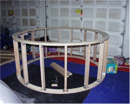
The base platform comes
together:
The day after thanksgiving I felt much better and felt like I had to get out and do some work. I got really productive. I cut out the patterns for the foundation and base rings, laminated them and attached them together with 16 2�x4�x3�, 64 steel L brackets and 256 drywall screws. The result is I now have the platform to start the mechanical work for the automated rotation.
The Electronics:
As this was coming together I realized that the electronic portion of the project was behind schedule. I worked out a circuit for an optical encoder wheel and after some debugging on the oscilloscope I got it working on the PIC 16f877. I have chosen the 16f877 as the processor for the project because of its large memory, PCM support, hardware serial ports (no bit banging and fast interrupt driver multi-channel serial) and lots of IO pins. The plan is to have a encoder wheel to track the dome position, with a �home� sensor and two �warning� sensors just short of home on either side. This will allow me to calibrate the home, interpolate the dome�s rotational position on the fly, and home the dome quickly, slowing dome when I hit the warning sensors. I am considering dropping the warning sensors if the software calculation of the dome position with the optical encoder wheels works within a few inches of perfect tracking. I don�t know what the slippage would be, but if the calibration is off you could race by the home sensor and be going to fast to stop. I want to be able to vary the speed on the dome motors so I can soft start it, and cost down when I am approaching the destination on a shuffle (following a slew, etc.). To that end I purchased a electron speed controller from a hobby store. It is the kind used for Remote Control Racing cards. It uses a pulse width modulation input and gives a continuously variable speed output with no mechanical components. This will allow me to control the dome rotation and shutters thru relays with a speed ramp, instead of just zapping full voltage across the relay contacts when I start and stop the dome. This should give the gearboxes better life and give me smother, less shocking motion control. (Postscript: The Warning sensors and R/C speed controller were dropped in favor of my home-brew built in speed controller)
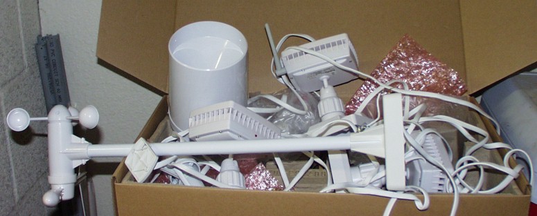
I am planning inputs from the LX-200, the controlling PC, sensors for the home position, home approach warning, shutter position, lockdown latch confirmation sensors and a hand box control. The electronics box will control the shutter mechanism, dome rotation tracking, electronic positioning of the dome, slaving the dome to the telescope input, backlit LCD output of current state and tracking information, interaction thru the hand box, operation of the lockdown latches, and interaction with the host PC that can remote control any of the dome functions. For now weather interlock will be a host-PC software function. I plan to have a dedicated Full-Time PC watching the dome and telescope. With the PC present there is no need for a hardware interlock on the control board. I may put the functionality in the hardware, but the weather station. I wrote a NT service called WxService monitors my Radio Shack Weather station and provides a scriptable COM interface to all the weather data. I will publish the service after some more testing and revision. In the meantime I put up a simple weather page that outputs some of the data it collects. I will add the fancy graphics later.
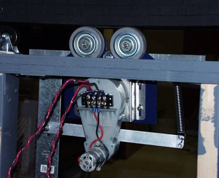
Rotation Motors
Installing the rotation motors was going to be tricky. It was not rocket science, but it did require lifting the dome on and off several times. This called for help. I send out a note to the "Space and Astronomy" public folder and John Kennedy and Dave Crosier came to the rescue. They helped me machine the aluminum supports, come up with the a better design for the self centering and helped fabricate and install the first motor mount. I copied the work for the second and thru the switch.It worked like a champ.
I have now installed the centering wheels. They worked nicely and with only 4 installed the dome rotated pefectly. There was no binding at all and they kept perfect center even with one motor disconnected. I installed the others for a total of 8. I was originally conserned abount these working, but it turns out the plan was fine.
Automation
The hardware design is getting close. I am hoping to send out for the first round of PC boards soon. I have built the prototype control board and have it up and running. I have writtien a skeleton ASCOM client that connects to the Desktop Universe hub and slaves the dome to the scope. This works really well. As things get moving, I will build a hub for the dome control so that it will work with any ascom telescope without the need for DTU or AC2.
I got away with using a single home sensor, and the quadrature encoding wheel works great. I have 1 degree resoultion for the dome tracking and good reliability. I am also working on the electronic speed control. I am designing my own circuit instead of using the R/C car one I bought. It cost to much and I can do the same thing with $5 in parts instead of the $100+ that the ESC units run for R/C cards. I think I can deal with about 15 amps at 12 volts.
At present I have the whole setup running against Desktop Universe and "The Sky" with the telescope Simulator tracking the virtual telescope. It can slew, track and train itself. It is prety basic, but functional right now. I will be adding the full features as time goes on.
The Observatory building
I realized I was going to need the control room built in order to mount the dome so I started working on framing the building. I demolished the infrastructure and partial wall/fence that went thru the building and framed it in with 2x4 stubs, 8x4 sheets of OSB, and sided it with siding that matched the existing walls. I have 3 walls up and all the materials needed to complete it. I need to pour the pier for the telescope and get the mount setup. I need to install the pier before I close the last wall and install the door. I will be putting in a full floor on the second level for the dome level. You will climb a ladder from the control room, thru a trap door and have access to the scope for maintanence and visual observing. The trap door will seperate the warm/lit area from the ambient/dark area. This also gives me the area under the dome in the control room as usable space.
The Pier
In order to support the stress from a nearly 10 foot hight pier, I needed allot of ballast underground. The current 6" slab would not do. I rented a concrete saw from Home Depot and cut out a 4x4 section. I also rented a jack-hammer and broke apart one section to allow me to remove the other sections of the slab neatly to reuse them. The largest section is not the front step, another is now 4' down supporting the rebar going up the column. I excavated appoximatly 4 feet down and left just a small lip around the edge. While at first I wanted to seperate the the slab from the pier base with foam or some other material, I found that the existing slab was more that 6" deep and the chace of vibration transmission was verry slim. During most photography I would not be in the building at all, and during visual observing I would be in the second floor isolated from the pier anyway.
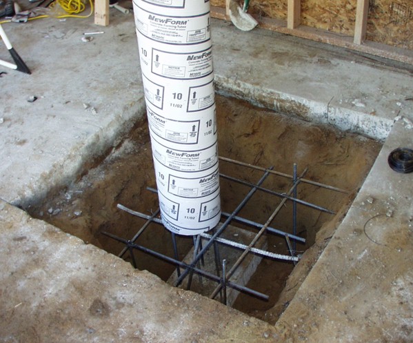
In the excavated pit I created a rebard framework wired together. I constucted a pier support using four 10 foot long sections of rebar wired togeter with four "X" shaped sections of rebar. This made sure the rebar would remain centered and vertical while we poured. The resulting section was dropped into the foundation hole and then a framwork arranged like a "tick-tack-toe" board was wired into the pier framework. Several other supporting pieces were wired to add support. After the framework was complete a 10' section of "Sonotube" was dropped over the pier rebar framework and set about a foot below the concrete line. This would create a plug in the end of the sonotube when we poured the base, allowing us to pour the pier tube later to avoid the hydrolic preasure from pusing out the concrete thru the base.
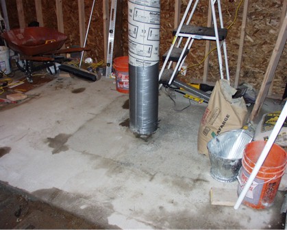
After the base was cured we poured the Pier. This required cutting a hole in the existing roof and hading a bucket at a time up the ladder to someone on the roof. I was petrified that the tube would blow out at the bottom. We kept a carpenters level handy and made sure we kept the tube perfectly vertical and supported during the pour. We added some 1/2" screen shaped into a 8 1/2" diameter cylender 4' tall to give some extra strength around the top where the mounting bolts would go since there would be a some gap between the rebar and the anchor bolts for the mount.
The anchor bolts were 3 1/2" L-bolts that were hung into the we concrete at the top of the tube. I bolted them onto a steele plate and placed the plate accross the top of the tube with the base of the bolts dropping generously into the concrete to about 1" of the threads. During the pour we used a long section of rebar to help make sure we got all the air pockets out by shaking the rebar up and down and working the concrete into the screen and any other potential pockets.
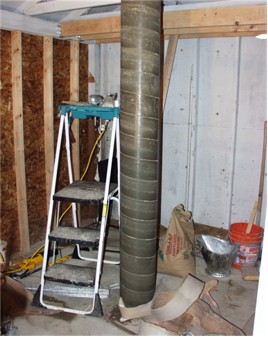
After 24 hours I removed the paper from the sonotube. It looked great. There were some small air pockets near the top where the screen had trapped some of the concrete, but not bad at all. Even with just 1 day of curing, it felt really solid. Concrete will take years to fully cure, but it should be hard enough to use in a week. It will continute to get stronger and stiffer over time.
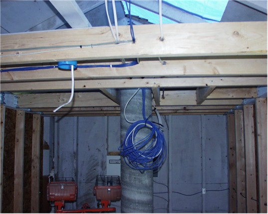
Platform for the Dome
The platform for the second floor is staring to come together. The floor is made up of 4x6 joists 12" on center with 3/4" plywood. There is a trap door engineered into the plan for access to the dome room. The next step I will have to remove about hald the existing roof to build the floor and mount the base ring, the rebuild the roof around it.
Last Updated Sunday Jan 26th, 2003.
A update a long time comming...
I have been so busy at work that I have not had much time to work on the observatory, combined with the rain and the fact that much of the work is out doors now, means thing have slowed a bit. But I have been able to make some progress.
I frames the front wall and then was able to sheath it and put up the siding. I installed a door and with the help of a friend who is an electritian we put in all the boxes, and wired all the low and high voltage lines. I also bug a 250' treach to tie in the power, phone, alarm and networking to the barn/apartment and thus also connect to thru existing wiring to the main house. I have 5 sets of cat 5 from the computer room downstairs to the telescope mount. One for telescope commands, one for autoguiding, one for color filter wheel, one for ethernet and one spare. Their are also extra pairs on the other 4 pairs for backup. I also have a USB cable for the camera.
I also have completely installed the joists for the base of the dome. I am waiting for clear whether to cut the hole for the dome base and seal the roof to the dome base cylender and mount the dome.
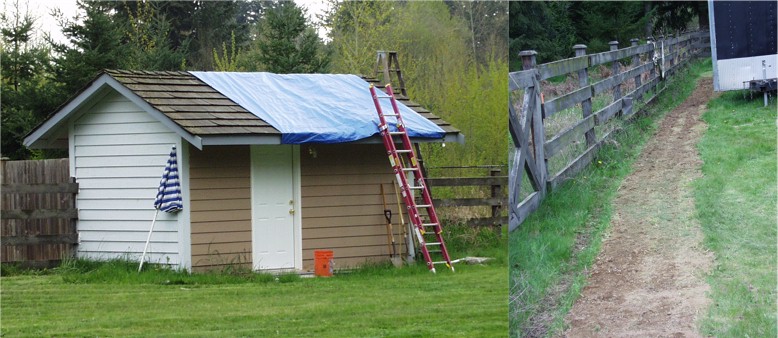
Here are the most current pictures. You can see the compled computer room. The blue tarp covers the hole in the roof where the dome base will mount. The trech on the right is part of the electrical conduit trench that takes a 250' path to the barn.
Comming together at last!
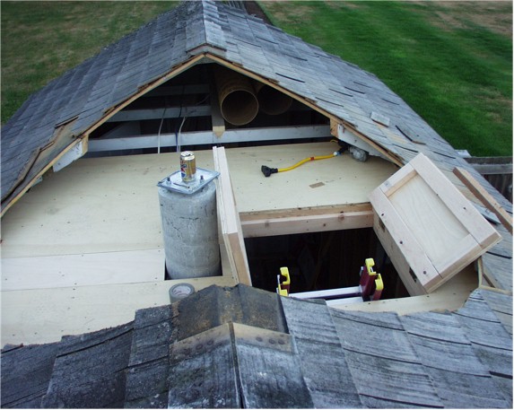
The hole in the roof.
I have finally taken time off from work to get the final push to put it all together into one project. I cut the hole for the dome base in the existing roof by putting a 3 way laser leveler on the end of a 3'11" 1x1 and I anchored one end to a nail in the center of where the hole would be, right at the peak of the roof. I used the leveled the other end and then traced the path of the laser on the roof as I spun the 1x1 gig around 360 degrees. This projected the circle onto the roof pitch. I then used a sawsall to cut thru the roof and then pitched the rubble and I had a nice hole just the right size for the dome base.
I put the floor for the observing level in and fabricated the trap door. This was allot more work that I thought but it is finally done.
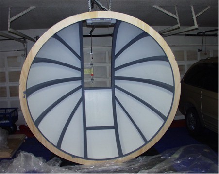
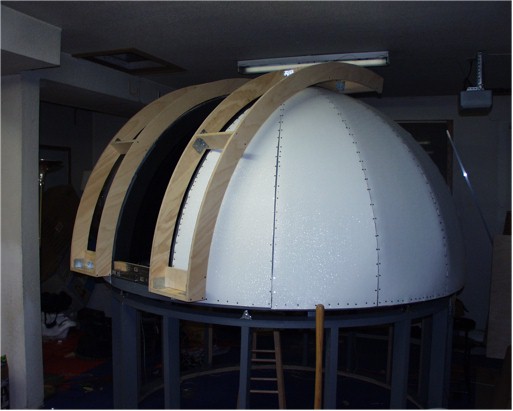
The shutters.
I had been putting off finishing the shutters for too long. On almost every other task I came up with one plan. On the shutters I had 3 different designs and I could not decide on which one to go for, they all had tradeoffs. In the end I settled on the most outragous of them. I really like the split shutter that the big observatories have like mount wilson. Even though I only have a 21' slit, I think they split shutter looks the coolest. It is also the hardest to get correct. I framed two simetrical sides of the shutters by taking 2 115 degree arcs traced out of plywood and connecting them together with four crossmembers. I used a set of roller bearing drawer slidders to rig the shutters and them carefully align them for a 1/3 inch gap all around. I will add weather stripping to make the final seal.

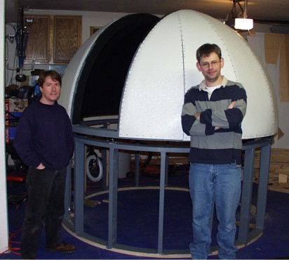
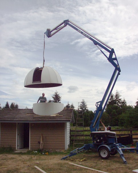
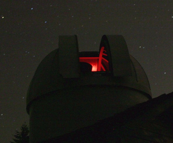
July 12th. The Dome is Raised!
Allot happened today. Reese, John, Tim, Rex and Craig all came out and helped get the dome out to the field and we rented a crane and hoisted it up on to the building. It looks great.
Later after everyone left I did all the weather seals as it started to rain. It let up and I installed the hangdown drapes to help keep driving rain out of the gap between the dome and the base.
Here is a nice night shot of the dome taking a long exposure shot taken with a Cannon 300D 6.3 Mpixel SLR
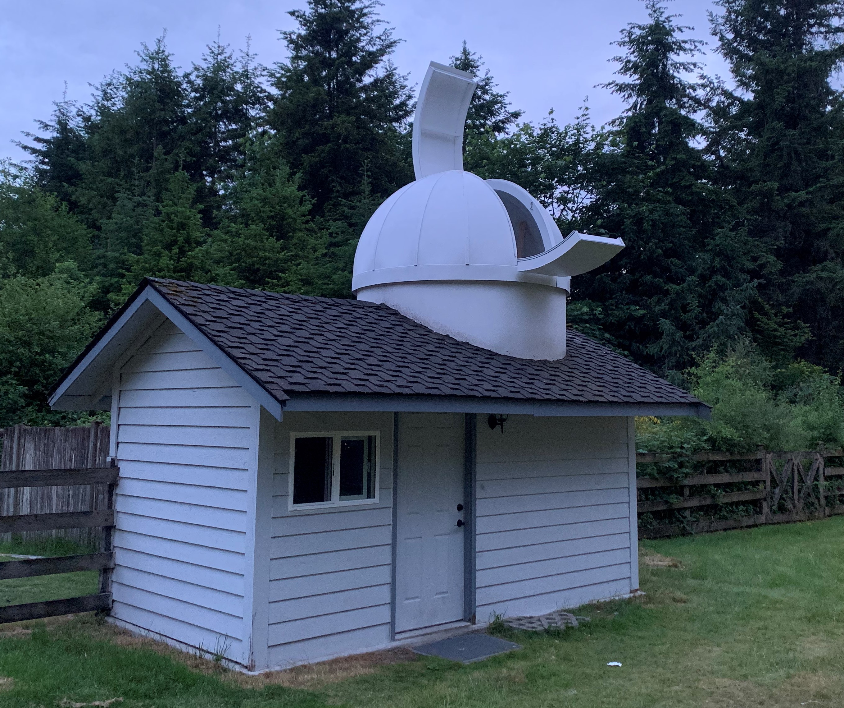
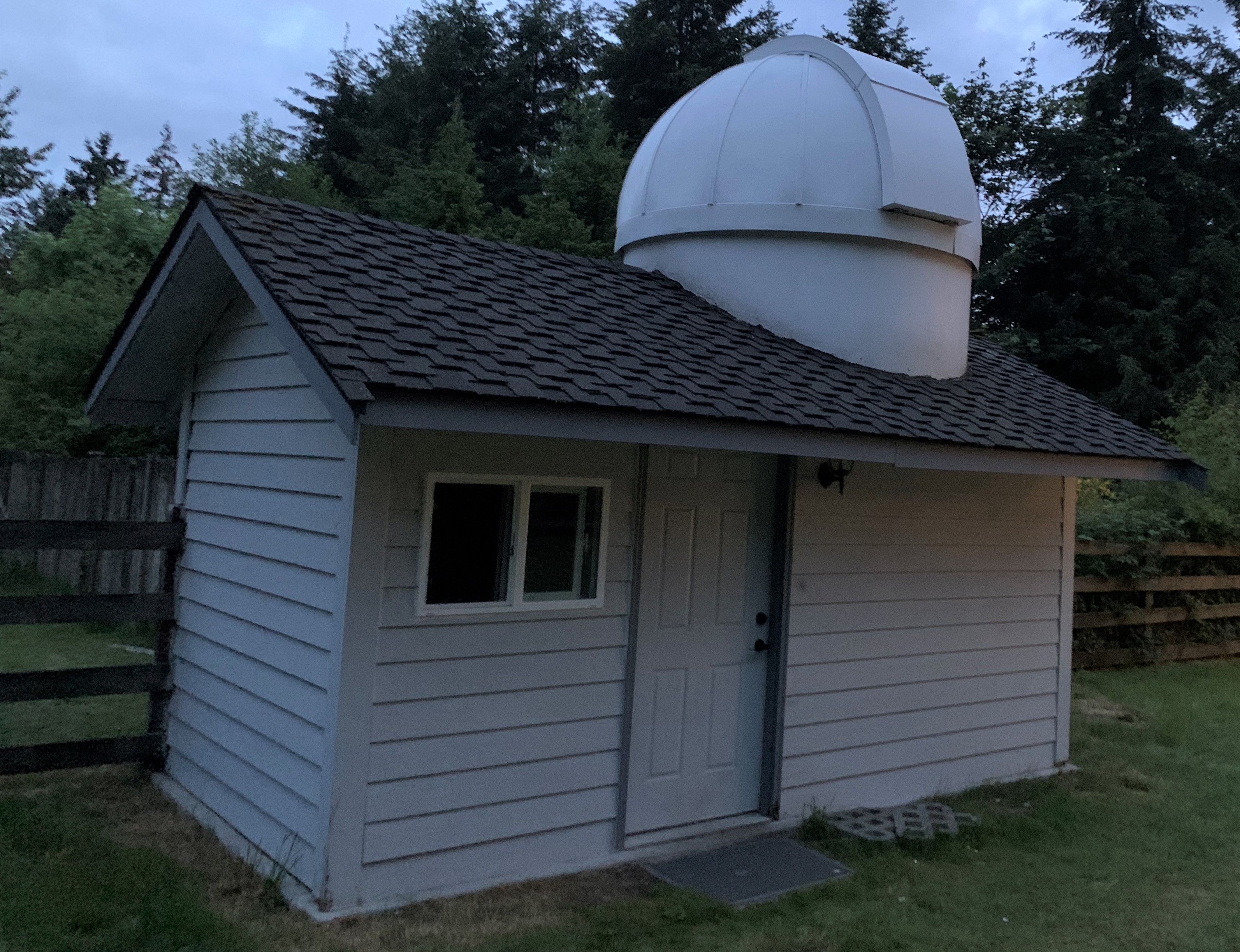
UPDATE July 2021 - The property with the obeservatory was sold. Since I would no longer be maitaining it I moved to a simplified design for the shutters and had a 1/3 Lower 2/3 Upper clam shell design that would offer better long term weather protection and allow easier opening for manual use.
Home | Observatory | Eos Driver Maxim/DL | Weather | Releated Links | Contact Us